

|

|

|

|

|

|

|

|

|

|

|

|

|

|

|

|

|

|

|

|

|

|

|

|

|

|

|

|

|

|
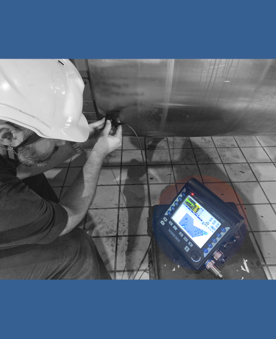
PA UT (PAUT): VLFS - Vertical Line Focusing Scanning
The typical applications relate to theinspection of:
- planar and circumferential narrow gap heavy thickness welds
- ER welds
- welded rails
- etc


|

This inspection software option is available for the ISONIC 3510, ISONIC 2010, and ISONIC 2009 UPA Scope instruments and featured with:
- Built-In Ray Tracer - Scanning Pattern (Scan Plan) Design
- Intuitive Image Guided PA Pulser Receiver with Beam Forming View
- True-To-Geometry Cross-Sectional Coverage (sectorial and / or linear) and line scanning along the desired line (for example, fusion line) either encoded or time based
- "On-the-fly" True-To-Geometry Whole Volume / Region of Interest (ROI) Overlay Volume Corrected Imaging:
- Cross Sectional Slices
- Top (C-Scan) View
- Side View
- End View
- 3D View
- DAC / TCG Data / Image Normalization
- Independent on TCG Angle Gain Compensation / Gain Per Focal Law Correction
- Automatic detecting of the maximal echo A-Scan among the plurarity implemented for providing of the cross-sectional material coverage
- Automatic Coupling Monitor
- 100% Raw Data Capturing
- FMC/TFM Protocol for the data acquisition and imaging
- Automatic Defects Alarming Upon C-Scan Acquisition Completed
- Automatic Creation of Editable Defects List
- Comprehensive Postrpocessing Toolkit Including:
- Recovery and Evaluation of the Captured A-Scans from the Recorded Cross Sectional Views and C-Scans
- Recovery of the Cross Sectional Views from the Recorded C-Scans
- Converting Recorded C-Scans or their Segments into 3D Images
- Off-Line Gain Manipulation
- Off-Line DAC Normalization of the Recorded Images / DAC Evaluation
- Numerous Filtering / Reject Options ( by Geometry / Position / By Amplitude db-toDAC / etc ) and Regeneration of the Corresponding of Editable Defects List and Storing it into a Separate FIle
- Defects Sizing
- Automatic creating of inspection reports - hard copy / PDF File
Compression wave cross-sectional coverage of the material with use of VLFS strategy combined with the RF A-Scan capturing ensures detection and distinguishing of the vertically oriented cracks and other planar sharp edges discountinuities. The said innovative modality also known as a reverse TOFD technique is based on the analysis of tip diffraction echoes providing high precision evaluation of the defects position and dimensions with use of a single probe / one side access only
The movies below illustrate detection and sizing of vertical and quasi-vertical oriented planar defects based on the reverse TOFD technique with use of ISONIC 3510 instrument
The movie below illustrates toggling VLFS S-Scan to FMC/TFM image whilst scanning the vertical resolution block with use of ISONIC 3510 instrument
Detection and imaging of the vertical crack developing from the ID side of the retainer ring of the power generation turbine rotor using VLFS SW application running in ISONIC 3510 unit is illustrated by the video below:
Note: In order to accelerate the data stream the videos above are linked to the Youtube. In case the YouTube may not be accessed from your location please use the links below

|
|
|
|

|
DOWNLOAD AND PLAYBACK THE EXEMPLARY INSTRUMENTS FILES
|
