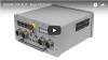
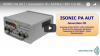
Super Powerful All-Weather-Operation Platform / Core Component for the Integration of Automatic Ultrasonic Inspection (AUT) Systems Combining Phased Array (PA), Conventional, and TOFD Modalities
Since 2007 ISONIC PA AUT - the super powerful all-weather-operation platform is used widely in the world as a core component of the integrated Automatic Ultrasonic Inspection (AUT) systems combining
Phased Array (PA), conventional, and TOFD modalities
Among the typical applications resolved by ISONIC PA AUT based automatic inspection systems are:
AUT of girth welds according to ASTM-1961
AUT of heavy thickness welds in the pressure vessels, reactors, etc according to radiography replacement codes
AUT of the railway axles and wheels
Immersion Ultrasonic Testing (IUT) of various materials and parts
IUT validation of the results obtained by various AUT machines
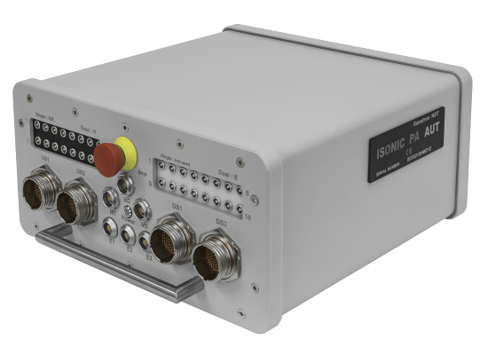
In March 2018 it was launched the next generation ISONIC PA AUT platform carrying the features listed below:
Fully parallel 128:128 (2 X 64:64 / 4 X 32:32) PA and 16 independent conventional / TOFD channels carried by portable light weight unit controllable either
over Ethernet OR directly using the standard PC keyboard and mouse
Expandable to 256:256 (2 X 128:128 / 4 X 64:64) PA functionality
Operating up to 4 PA probes and 16 conventional probes / pairs of probes simultaneously
Up to 4096 PA and 512 conventional / TOFD channels functionality thanks to the ability of multiple units operation (up to 32) controlled from one computer
Parallel A/D conversion and on-the-fly digital phasing and superimposing of PA elements signals, no multiplexing involved
Free settling of emitting and receiving aperture
Hardware / software synchronization
3 motor powering and control terminals
3 encoder terminals
Built-in UPS (uninterruptible power supply)
Emergency stop button
Rugged IP 67-sealed case mountable on scanner
All-Weather-Operation: -50°C ... +60°C
No intake air
No water or other type of cooling required
9 kg weight
ISONIC PA AUT - Technical Data
PA Modality
Structure:
1 X 128:128 / 2 X 64:64 / 4 X 32:32
1 X 256:256 / 2 X 128:128 / 4 X 64:64 - with use of the corresponding extension terminals
Initial Pulse:
Bipolar Square Wave with Boosted Rising and Falling Edges, Guaranteed Shell Stability, and Active Damping
Transition:
≤7.5 ns (10-90% for rising edges / 90-10% for falling edges)
Amplitude:
Smoothly tunable (12 levels) 50V … 300 V peak to peak into 50 Ω
Half Wave Duration:
50…600 ns controllable in 5 ns step
Emitting aperture:
1...32/64/128/256* adjustable as fully or partially matching OR mismatching with the receiving aperture
* - with use of the corresponding extension terminals
Receiving Aperture:
1...32/64/128/256* adjustable as fully or partially matching OR mismatching with the emitting aperture
* - with use of the corresponding extension terminals
Phasing - emitting and receiving:
0…100 μs with 5 ns resolution independently controllable
Analogue Gain:
0...100 dB controllable in 0.5 dB resolution
Advanced Low Noise Design:
85 μV peak to peak input referred to 80 dB gain / 25 MHz bandwidth
Frequency Band:
0.2...25 MHz
A/D Conversion:
100 MHz 16 bit
Digital Filter:
32-Taps FIR band pass with controllable lower and upper frequency limits; non-linear acoustics technique supported
Superimposing of receiving aperture signals:
On-the-fly, no multiplexing involved
Phasing (receiving aperture):
On-the-fly 0…100 μs with 5 ns resolution
Dynamic Focusing:
Supported
FMC, TFM, Back Diffraction Technique with / without and Mode Conversion:
Supported
A-Scan:
RF
Rectified (Full Wave / Negative or Positive Half Wave)
Signal's Spectrum (FFT Graph)
Reject:
0...99 % of screen height controllable in 1% resolution
Material Ultrasound Velocity:
300...20000 m/s (11.81…787.4 "/ms) controllable in 1 m/s (0.1 "/ms) resolution
Time Base - Range:
0.5...7000 μs - controllable in 0.01 μs resolution
Time Base - Display Delay:
0...400 μs - controllable in 0.01 μs resolution
Probe Delay:
Automatically settled depending on the PA probe / wedge / delay line in use according to the desired:
Aperture(s)
Incidence Angle
Focal Point Position
etc
DAC / TCG:
One Per Focal Law
Multi-curve
Slope ≤ 20 dB/μs
Available for the rectified and RF A-Scans
Theoretical – through entering dB/mm (dB/") factor
Experimental – through recording echoes from several reflectors; capacity - up to 40 points
Automatic Gain Correction:
Complimentary Mechanism Independent on DAC / TCG:
AGC - Angle Gain Compensation for the sectorial scan coverage
GPSC - Gain Shot (Focal Law) Correction for other types of coverage
EquPAS - Equalized PA Inspection Sensitivity:
Provided for every desired type of reference reflector:
SDH (Side Drilled Hole)
FBH (Flat Bottom Hole)
EDM Notch
etc
Gates:
2 Independent gates per focal law controllable over entire time base in 0.1 mm /// 0.001" resolution
Threshold:
5...95 % of A-Scan height controllable in 1 % resolution
Phased Array Probes:
1D Array – linear (LA), rings (RA), and the like
Dual Linear Array (DLA)
Matrix Array (MA)
Dual Matrix Array (DMA)
Focal Laws:
8192 in total
Independently adjustable gain / time base / apertures / pulsing receiving modes, etc for each focal law among the plurality of implemented within a frame composing sequence
Other type of motor / PC power voltage / Extra-motors - on request
Power:
Mains - 100…240 VAC, 40…70 Hz, auto-switch
36...72 VDC
Built-in UPS (uninterruptible power supply)
Ambient Temperature:
-50°C ... +60°C (operation)
-50°C ... +60°C (storage)
Housing:
Rugged aluminum case mountable on scanner
IP 67
No air intake
No external cooling required
Dimensions of electronic box:
305X160X380 mm (12.00"x6.30"x14.96")
Weight:
8.890 kg (19.56 lbs)
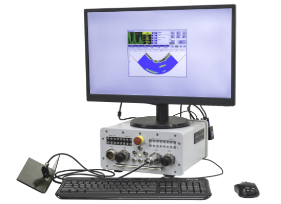
Desktop UT Workstation
Thanks to the powerful on-board W7PRO computer with Dual Core Intel Atom N2600 1.6 GHz CPU, 2 GB RAM, and 64 GB SSD drive carried by the latest ISONIC PA AUT platform
in addition to numerous AUT applications it may be used as very powerful stand-alone Desktop UT Workstation, suitable for using as:
Laboratory masterpiece equipment running all PA inspection applications implemented by Sonotron NDT portable PA flaw detectors
ISONIC 3510, ISONIC 2010, and ISONIC 2009 UPA Scope
Core-element for the in-factory inspection stations
FMC/TFM:
Inspection SW application MULTIGROUP T for the portable PA instruments and platforms of ISONIC Series carrying the Dual Core Intel Atom N2600 CPU 1.6 GHz internal computer card
(ISONIC 3510 – all units, ISONIC 2010 units manufactured after April 30, 2017, ISONIC 2009 UPA-Scope units manufactured after May 31, 2017,
and ISONIC PA AUT units manufactured after March 1, 2018) for the first time ever provides performing of the regular or true-to-geometry Sectorial Scan (S-Scan) coverage with / without
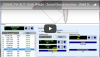
involvement of cross-sectional sensitivity equalizing (EquPAS) along with the FMC/TFM coverage for the simple and complex geometry welds and other structural elements. The instrument screen video illustrating
the live S-Scan and FMC/TFM coverage and imaging is present below:
Availability of both complimentary approaches, namely FMC/TFM and EquPAS, in the same instrument allows the inspection organizations finding the optimal solutions for their daily practice
Note: In order to accelerate the data stream the videos above are linked to the Youtube. In case the YouTube may not be accessed from your location please use the link below
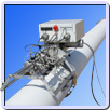
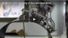
All Weather High Productivity Automatic Ultrasonic Inspection of Girth Welds Using Zonal Discrimination According ASTM E-1961
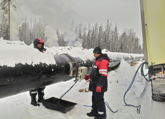
In the newly constructed gas and oil off-shore and on-shore pipelines the pipes are girth-welded automatically then rapidly inspected, coated, and buried. Detection, evaluation, and repair of defects in the welds should be
performed very quickly in order avid the affecting of the construction cycle therefore the high-speed automatic ultrasonic testing (AUT) of girth welds is incredibly demanded as sole codes accepted alternative to radiography
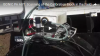
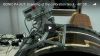
AUT is implemented through scanning of the weld along the fusion line using several probes situated on the OD surface from both sides of girth weld. Traditionally the frame
carrying the ultrasonic probes and position encoder is fitted into the traction unit (scanner) moving along the orbital travel band and the umbilical connects probes, position encoder,
and scanner’s motor to ultrasonic pulsing-receiving, control, data processing and recording electronics, which is placed either in the truck cabin (on-shore inspection) or in a separate room on the
lay barge (off-shore inspection) at the distance of up to few tens meters from the scanning deck. A team of the operators handles the AUT system: usually there are two operators (scantechs) involved
into the placement of scanning stuff onto the pipe and one operator is responsible for control of the scanning, observation of the indications and recording process, and taking GO/NO GO decision
AUT of girth welds is regulated by a couple of codes such as ASTM E-1961, API 1104, DNV-OS-F101, and DNV-RP-F118, according to which the weld volume is divided into multiple horizontal thin slices (zones) in the cap, fill, hot pass, and root areas.
The designated zones are insonified one by one through implementing of the sequence of independent pulsing-receiving shots. Use of phased array (PA) technology significantly minimizes quantity of probes involved into
multiple zone insonification thanks to electronic beam steering. This simplifies scanning stuff and accelerates the inspection. Use of several TOFD and conventional probes simultaneously with PA probes
provides complete coverage of the weld volume at every cross-sectional position along the fusion line: the PA probes do implement pulse echo and tandem technique for the detection of various compact and longitudinal defects;
the conventional probes perform inspection for the detection of transversal defects (K- and X- schemes), detection of laminations in the heat affected zone in parent material, etc.;
TOFD probes implement complimentary technology allowing detection of the compact and longitudinal defects through receiving of the diffracted signals. The ability of defect detection in each zone is provided through
calibrating of the system on the specially manufactured Z-cut blocks containing certain number of artificial reflectors, which’s location, orientation, shape, and dimensions represent variety of flaws to be sensed and recorded
The practical use of the traditional PA AUT stuff over several years highlighted a number of inconveniencies experienced by the inspection providers:
Big expensive, heavy, bulky, and vulnerable umbilical causing relatively high operational cost as well as low signal to noise ratio and high power consumption due to transfer of analogue signals through tens meters length wires
Insufficient quantity of A/D converters leads to use of multiplexing and elevating pulse repetition rate further increasing power consumption
Insufficient quantity of pulsing-receiving channels requires more than one scanning revolution and / or making compromise by using the wedges of PA probes also for TOFD to inspect single girth weld completely,
this slows the overall speed of AUT
Overheat of electronics caused by high power consumption requires water-cooling or frequent shutdown breaks during work shift
First introduced in 2007 ISONIC PA AUT system from Sonotron NDT represents cutting edge technology solution for high-speed AUT of girth welds bringing practical implementation to the highest convenience level
For the first time ever:
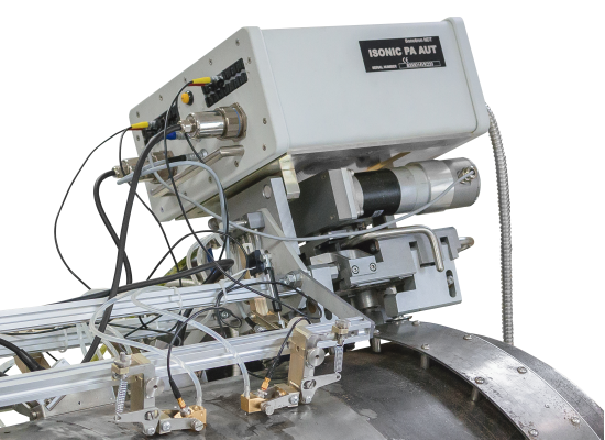
the electronics of ISONIC PA AUT packed into rugged portable light weight (6.8 kg only) IP 67sealed case was fitted into the same scanner frame that carries the probes and encoders
the regular remote PC connected to the instrument through Ethernet provides full control, data acquisition and imaging in real time, thus no big expensive, heavy vulnerable umbilical
– just thin and very light weight armored tube carries DC wires and LAN cable, which are connected to the machine through the specially designed rotating terminal
the probes signals are sampled and pre-processed in real time on-board; the digitized raw inspection data is transferred then to the to remote PC for further processing,
storage, and imaging: fully digital through-Ethernet control and data transfer provide practically unlimited length of distance to the remote PC providing the flexibility of creating control rooms or multiple monitor stations
throughout the barge / factory / weld station, etc
the probes are connected to ISONIC PA AUT using short cables – comparing to transfer through long umbilical this provides much better signal quality significantly improving the signal to noise ratio and dynamic range
Further improvement of the signal to noise ratio and dynamic range is achieved through firing probes with unique bi-polar square wave initial pulse reaching up to 300 Volt peak to peak for PA probes and up to 400 Volt peak to peak
for the conventional and TOFD probes. The duration and amplitude for both positive and negative half-waves of the initial pulse may be tuned in wide range. Additionally it is provided high stability of firing amplitude settled by an
operator whilst the leading and falling edges of bi-polar initial pulse are electronically boosted
there is no limit for the quantity of PA probe elements composing emitting aperture – if necessary all elements of each PA probe connected to ISONIC PA AUT may fire simultaneously
the advanced low noise design provides the ability of up to 100 dB analogue Gain for PA, TOFD, and conventional probes
ISONIC PA AUT performs 16-bit 100 MHz sampling rate digitizing of signals obtained by all elements of receiving aperture at parallel independently on their quantity (aperture size) – there is no multiplexing involved;
the digitized signals are phased (phase-shifted) and superimposed on-the-fly according to the desired focal law so each superimposed A-Scan is formed and memorized in the hardware buffer in real time during the entire pulsing-receiving shot (focal low)
ISONIC PA AUT performs complete raw data capturing allowing play-back of all A-Scans obtained during the scanning; this provides full compliance with ASME 2235 Code Case related to the use of ultrasonic inspection in lieu of radiography
the rational power management eliminates heating problem; thanks to extremely low power consumption there is no intake air, water or other type cooling is required for the ISONIC PA AUT
in the ISONIC PA AUT each pulser receiver for TOFD and conventional probes may be operated in both modes – dual and single, i.e. use of dual element probes, TOFD insonification, K- and X-scheme for pitch-catch detection of transversal
defects with shear waves, etc employ only one channel per task
typically ISONIC PA AUT comprises 128 PA channels allowing simultaneous use of two 64-elements probes and 16 conventional channels, which are totally separated the from PA stuff;
it is upgradeable to 4096 PA / 512 conventional channels functionality thanks to multiple units operation (up to 32) controlled from one computer. This unique feature might be useful for the
future state of the art use, for example matrix PA technology allowing 3D beam steering vs today’s 2D
Note: In order to accelerate the data stream the video above is linked to the Youtube. In case the YouTube may not be accessed from your location please use the link below
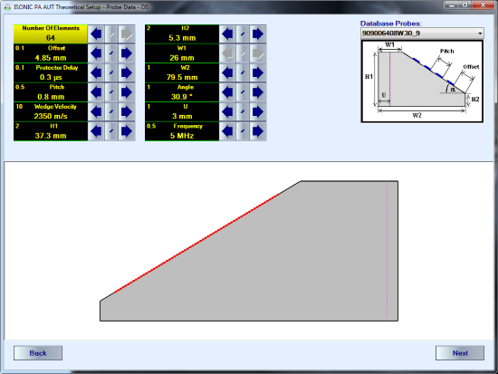
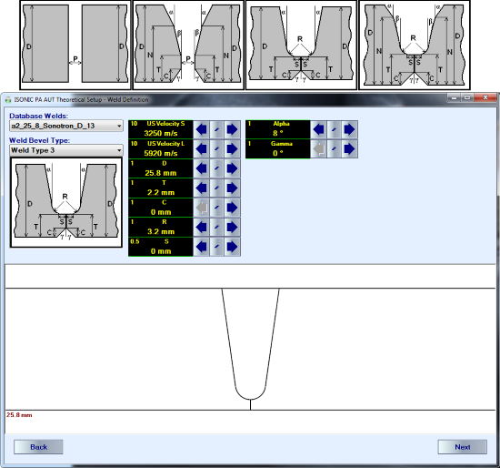
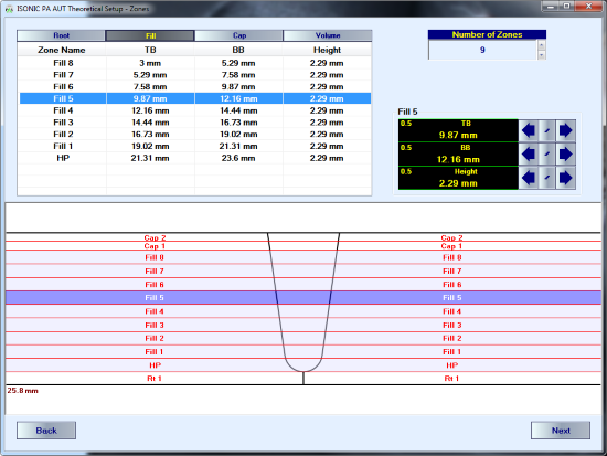
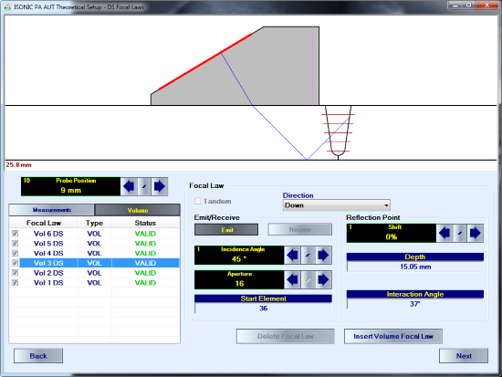
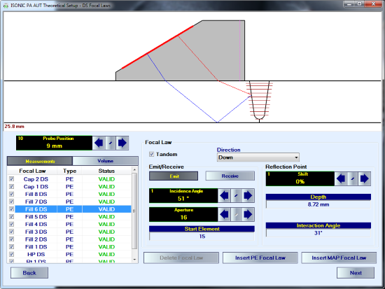
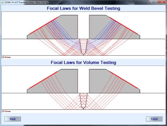
Theoretical rays tracing procedure is required for operating of PA probes – it is necessary to cover weld bevel surface and weld volume completely. Ray tracing for the ISONIC PA AUT is performed through the
very intuitive Theoretical Setup Wizard routine in a number of simple steps:
Probe Definition dialogue for entering parameters of PA probes and wedges
Weld Definition dialogue for selection of appropriate weld bevel from data base and entering related geometry and dimensions
Zones Definition dialogue for "slicing" of weld volume, cap, hot pass, and root areas into zones to be insonified in each qualified position of PA probe:
Ray Tracing dialogue for determining of zone-by-zone insonification scheme (pulse echo or tandem; incidence angles; emitting and receiving aperture; focal distance) and appropriate positions for PA probes
from both sides of the weld (Upstream – Downstream)
Thanks to the extremely friendly user interface, simplicity of operation, and high degree of automation of the Theoretical Setup routine
the weld bevel definition and ray tracing are performed in the extremely short time. Some moments of the routine are reflected in the screen video below:
Note: In order to accelerate the data stream the video above is linked to the Youtube. In case the YouTube may not be accessed from your location please use the link below
Ultrasonic setup is performed on the specially manufactured Z-cut blocks containing certain number of artificial reflectors, which’s location, orientation, shape, and dimensions represent variety of flaws to be sensed and recorded.
The calibration blocks are manufactured for each pipe diameter (OD), wall thickness (WT), weld bevel, etc. in a manner providing the detectability and recording of all artificial defects a single full or partial revolution
scan along the hypothetic fusion line. Typically the calibration block is shaped as piece of pipe allowing setup of all scanning stuff; each cross-section section containing the artificial defect is marked on the OD surface
of the pipe accordingly
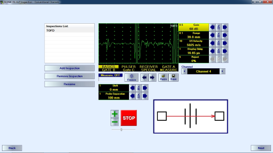
The initial goal is one-by-one placement of the appropriate probe either PA, TOFD, or conventional into every predefined positions and providing the necessary settings
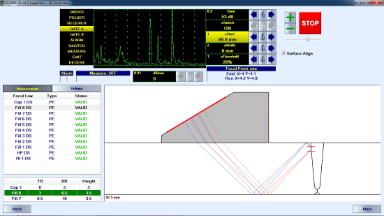
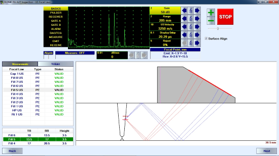
(Gain, Gate, Aperture, etc) ensuring detection and resolving of all artificial defects. The process is illustrated by the short video and typical screenshots below:
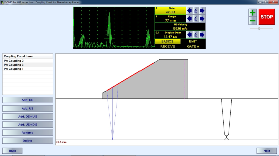
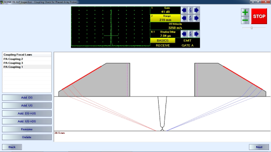
A number of additional pulsing receiving shots should be calibrated for the PA and conventional probes with the purpose of the continuous coupling monitoring.
For the PA probes ISONIC PA AUT allows using of the longitudinal wave back wall echo and / or the signal through-transmitted from one PA probe to another as a reference for the coupling monitor
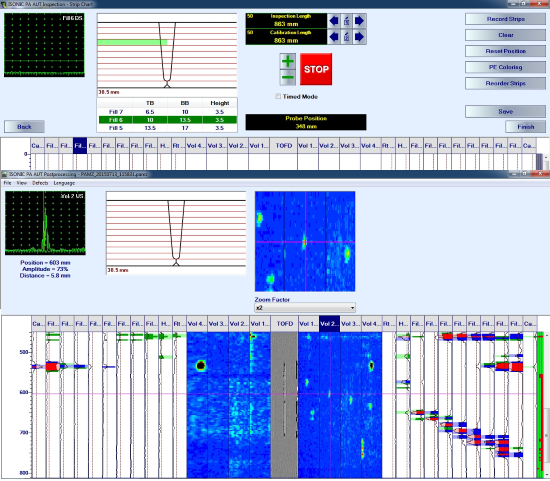
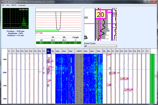
The final screen of Ultrasonic Setup Wizard relates to the configuration of the strip chart.
Strip chart is a way of AUT data presentation whereas each pulsing-receiving shot is continuously recorded into corresponding strip
ISONIC PA AUT allows forming the strips of the following types:
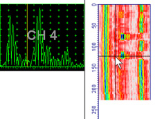
PE
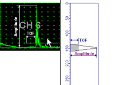
Amplitude / TOF Pulse Echo Strip represents peak amplitude and time of flight for signals matching with Gate and exceeding it’s threshold level
Position of Amplitude Line on the strip is proportional to the signal height. Echo amplitude equal or exceeding 100% of A-Scan height brings Amplitude Line trace to full strip width level Width of gray Time of Flight (TOF) Rectangle is proportional to the signal position in the Gate. For signals, which’s time of flight measurement point matches with the Gate end width of gray Time of Flight (TOF) Rectangle is equal to the full strip width For geometry echoes matching within specially designated Gate Tail the Amplitude Line is not produced, just TOF Rectangle
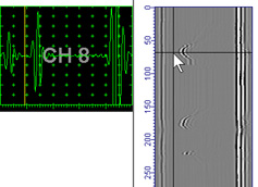
MAP
Up to 256 Colors Palette Map Strip represents sequence of A-Scans whereas color of points for each horizontal line is coded according to corresponding signal level and default palette
TOFD
256 gray levels TOFD strip represents sequence of RF A-Scans whereas brightness of points for each horizontal line is modulated according to corresponding signal level
Coupling
Coupling Strip is formed through comparing amplitude of reference signal with the gate threshold. Green Sufficient Coupling record is provided for signals exceeding gate threshold; red Insufficient Coupling record is provided in opposite case
Reshaping of the Strip Chart is possible through manipulating position / lateral displacement of each strip according to the probes fitting into the scanning frame:
The Calibration Scan is performed then in the automatic mode in order to ensure the sensing and resolving of all artificial defects and recording them at the right positions
Ultrasonic Setup Wizard is completed with creating of the final Inspection Setup File; the routine inspection becomes possible at any moment since the said file is uploaded into control computer
The movies illustrating scanning of calibration blocks:
Note: In order to accelerate the data stream the videos above are linked to the Youtube. In case the YouTube may not be accessed from your location please use the links below
Scanning and Postprocessing
Usually prior to starting the projects the contractors should pass through the team validation process (team = equipment + inspection procedure + team of operators). At that stage there is a number
of the weld samples with the natural defects to be inspected and the inspection report including the measurements and interpretation results to be issued by the team. Comparison of the presented report with the
results obtained through the destructive test of the same welds followed either by macroslicing or immersion ultrasonic testing (IUT) of the weld rings is a platform for the validation. The video below illustrates the
inspection of the weld sample with natural defectS at the stage of validation according to DNV-OS-F101 / DNV-RP-F118:
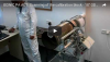
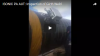
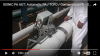
Movies illustrating scanning of the girth welds in the field:
`
`
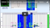
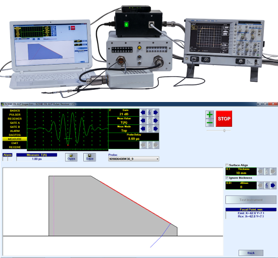
Whilst scanning the raw data A-Scans obtained by PA, conventional, and TOFD probes are transferred to the control PC along with the corresponding encoded position data.
The control PC provides the raw data recording and forms the strip chart in real time. Whilst scanning the operator may observe the live A-Scans for every strip.
The inspection results file comprising the fully recorded raw data bulk for the weld and the last valid calibration is created automatically upon the scanning of the weld completed
At the postprocessing stage it is possible to play back the captured A-scans, mark, size, and evaluate defects, create defects list, etc
Some moments of Postprocessing are illustrated by the screen video below:
Note: In order to accelerate the data stream the videos above are linked to the Youtube. In case the YouTube may not be accessed from your location please use the links below
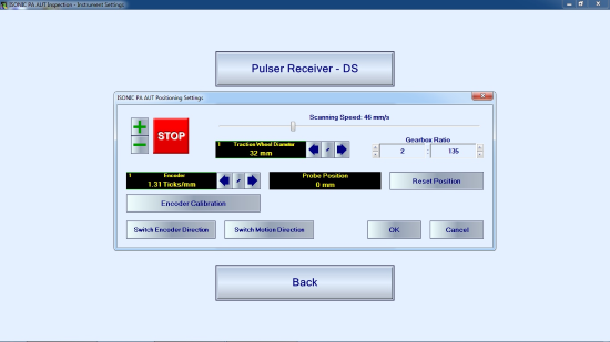
Built-in Utilities
Entering scanner parameters (gearbox rate, driving wheel diameter), encoder calibration and entering scanning speed are performed in dialogue mode through the simple user interface
Every probe either PA, conventional, or TOFD may be driven independently through the corresponding pulser receiver screen. This feature is very useful for the various purposes such as
verification of wedges, studying of phased array focusing effects, etc
Automatic Ultrasonic Inspection of Welds Combining Multigroup Sectorial Scan, Linear Scan, FMC/TFM, Tandem, TOFD, and Conventional PE and Pitch-Catch Coverage
Use of above noted coverage plans in any desired combination is applicable to the automatic ultrasonic inspection of:
planar butt welds with symmetrical and asymmetrical bevel
circumferential butt welds with symmetrical and asymmetrical bevel
longitudinal welds (long seams)
spiral welds
An exemplary video is shown below:
Note: In order to accelerate the data stream the video above is linked to the Youtube. In case the YouTube may not be accessed from your location please use the links below
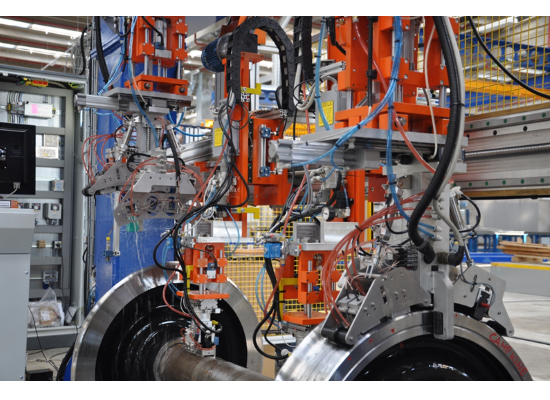
Automatic Ultrasonic Inspection of the Railway Axles and Wheels Combining PA and Conventional Modalities
2 X 64 elements PA probes are used for the inspection of the wheel seat areas from one or both sides and the whole shaft for the transversal cracks. High sensitivity and signal to noise ratio along with the sharp imaging are
achieved through sharp beam focusing provided through use of the emitting and receiving aperture comprising all 64 elements of the probe. The focal point migrates along the axle surface opposite to the placement of the PA
probes. The sensitivity across the entire cross section is equalized through use of angle gain compensation and DAC (or TCG) normalization so the echo amplitudes from the equal transversal defects differ not more than 1 dB
from the DAC (or from each other in case of using TCG) independently on their location along the axle. True-to-Geometry cross section imaging is provided along with 100% raw data capturing and strip chart recording
Conventional probes are used for the complimentary inspection of the axle material in PE or TT mode or of the wheels. Up to 16 conventional probes either single or dual element or pairs of probes may be used
simultaneously with a pair of PA probes. While scanning the A-Scans related into conventional probes are stored and represented in the same strip chart with the PA data
Depending on the scanning plan the complete inspection may be completed in a single revolution of several revolutions, each revolution lasts about 30 seconds so the inspection of the whole wheelset
including loading into / pushing out of the scanning frame lasts just very few minutes
The postrpocessing routine is featured with creating of the editable defect list, play back of every desired A-Scan, off-line gain manipulation, defect sizing, A-Scan evaluation, etc
Depending on the desired / required scan plan it is possible to inspect from 60 to 150 wheelsets daily
The real inspection site video examples:
Note: In order to accelerate the data stream the videos above are linked to the Youtube. In case the YouTube may not be accessed from your location please use the links below
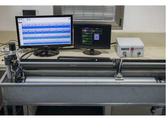
Immersion Ultrasonic Inspection (IUT) Combining PA and Conventional Modalities
IUT - tubular parts
One or two matrix array probes inspect the tubular part for the transverse, longitudinal, inclined cracks providing 3D beam steering each. The strip chart (PE or Map)
is recorded for each focal law implemented. Use of matrix array probes minimizes the footprint to the value avoiding the dead ends independently on the number of
the azimuth of pulsing receiving. The defect list if formed in real time whilst scanning and represents position and dimensions of each inhomogeneity detected.
The raw data capturing is provided so every A-Scan obtained during the inspection may be reproduced at the postprocessing stage. At the postprocessing stage
it is also possible to manipulate gain and gate settings for each focal law independently on others and generate the new defect list accordingly
Inspection video
IUT in lieu of macro-slicing: the circumferential girth weld rings cuts
This is a typical application related to the validation of AUT systems and teams for the inspection of girth welds. Since the scanning of the girth welds samples with the preprogrammed defects by various AUT systems and teams is completed
it is necessary to validate the results. The traditional macro-slicing is very expensive and time consuming operation thus the validation centers switch to much rapid and economically justified IUT of the rings cut offs including the weld
and heat affected zone areas. The IUT is performed with use of PA probes either matrix or linear array or conventional immersion probes, or combining 2 modalities. The smart XY- and turntable scanning strategies are supported
The results of IUT scanning performed with the resolution of 0.2 mm are presented in real time as multilayer C-Scan; 100% raw data storage is provided. The postprocessing is featured with the automatic creating of the defect list and
sizing of each defect (position and length along the fusion line measured above the OD surface of the pipe, depth and height), recovery of the A-Scans, off-line Gain manipulation, etc. In addition every defect cross section of the ring may be presented
in the form of virtual macroslice allowing quick distinguishing between various defects. The defect list is exportable into the common format spreadsheet file (MS Excel) making it possible further comparison with the results presented by
the systems / teams under validation through the simple automatic overlap
Inspection videos
Postprocessing video
Note: In order to accelerate the data stream the videos above are linked to the Youtube. In case the YouTube may not be accessed from your location please use the links below


 Amplitude / TOF Pulse Echo Strip represents peak amplitude and time of flight for signals matching with Gate and exceeding it’s threshold level
 Up to 256 Colors Palette Map Strip represents sequence of A-Scans whereas color of points for each horizontal line is coded according to corresponding signal level and default palette
 256 gray levels TOFD strip represents sequence of RF A-Scans whereas brightness of points for each horizontal line is modulated according to corresponding signal level
 Coupling Strip is formed through comparing amplitude of reference signal with the gate threshold. Green Sufficient Coupling record is provided for signals exceeding gate threshold; red Insufficient Coupling record is provided in opposite case


 2 X 64 elements PA probes are used for the inspection of the wheel seat areas from one or both sides and the whole shaft for the transversal cracks. High sensitivity and signal to noise ratio along with the sharp imaging are
achieved through sharp beam focusing provided through use of the emitting and receiving aperture comprising all 64 elements of the probe. The focal point migrates along the axle surface opposite to the placement of the PA
probes. The sensitivity across the entire cross section is equalized through use of angle gain compensation and DAC (or TCG) normalization so the echo amplitudes from the equal transversal defects differ not more than 1 dB
from the DAC (or from each other in case of using TCG) independently on their location along the axle. True-to-Geometry cross section imaging is provided along with 100% raw data capturing and strip chart recording
2 X 64 elements PA probes are used for the inspection of the wheel seat areas from one or both sides and the whole shaft for the transversal cracks. High sensitivity and signal to noise ratio along with the sharp imaging are
achieved through sharp beam focusing provided through use of the emitting and receiving aperture comprising all 64 elements of the probe. The focal point migrates along the axle surface opposite to the placement of the PA
probes. The sensitivity across the entire cross section is equalized through use of angle gain compensation and DAC (or TCG) normalization so the echo amplitudes from the equal transversal defects differ not more than 1 dB
from the DAC (or from each other in case of using TCG) independently on their location along the axle. True-to-Geometry cross section imaging is provided along with 100% raw data capturing and strip chart recording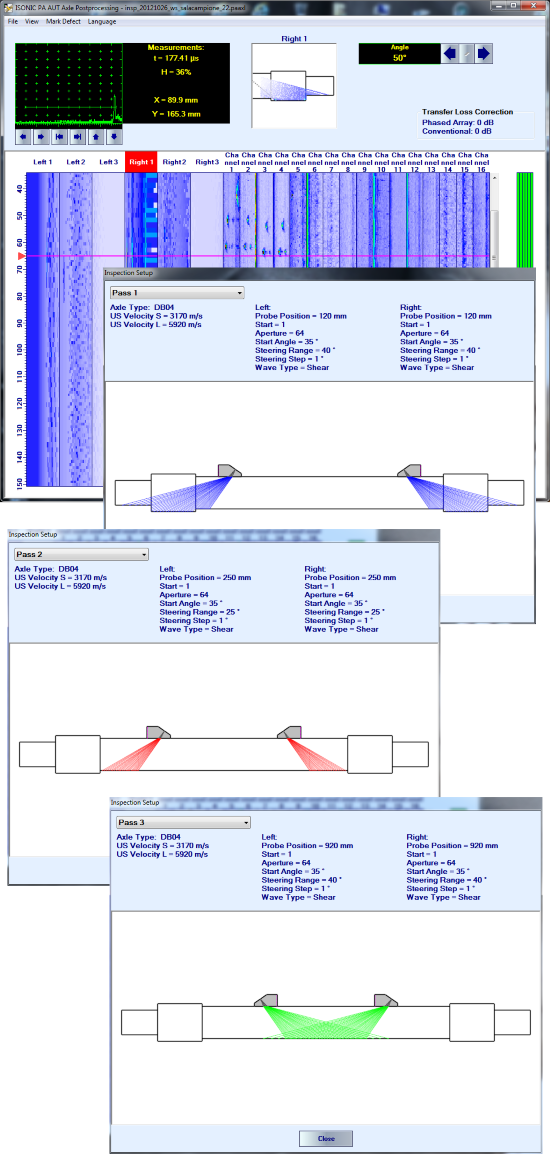

 One or two matrix array probes inspect the tubular part for the transverse, longitudinal, inclined cracks providing 3D beam steering each. The strip chart (PE or Map)
is recorded for each focal law implemented. Use of matrix array probes minimizes the footprint to the value avoiding the dead ends independently on the number of
the azimuth of pulsing receiving. The defect list if formed in real time whilst scanning and represents position and dimensions of each inhomogeneity detected.
The raw data capturing is provided so every A-Scan obtained during the inspection may be reproduced at the postprocessing stage. At the postprocessing stage
it is also possible to manipulate gain and gate settings for each focal law independently on others and generate the new defect list accordingly
One or two matrix array probes inspect the tubular part for the transverse, longitudinal, inclined cracks providing 3D beam steering each. The strip chart (PE or Map)
is recorded for each focal law implemented. Use of matrix array probes minimizes the footprint to the value avoiding the dead ends independently on the number of
the azimuth of pulsing receiving. The defect list if formed in real time whilst scanning and represents position and dimensions of each inhomogeneity detected.
The raw data capturing is provided so every A-Scan obtained during the inspection may be reproduced at the postprocessing stage. At the postprocessing stage
it is also possible to manipulate gain and gate settings for each focal law independently on others and generate the new defect list accordingly