| Number of Channels: |
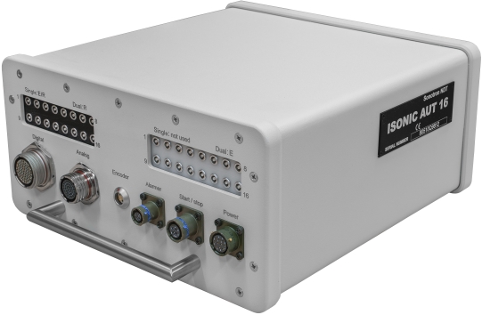
16 - ISONIC AUT 16
32 - ISONIC AUT 32 |
| Pulsing/Receiving (multi channel operation): |
Parallel - all channels do fire, receive, digitize, and record signals simultaneously
Sequential ñ cycles of firing, receiving, digitizing, and recording signals are separated in time in a sequence loop for:
- Each channel
- Each group of channels working at parallel
|
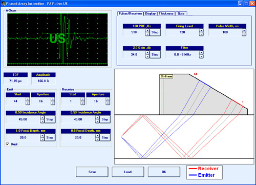
| Initial Pulse: |
Bipolar Square Wave with Boosted Rising and Falling Edges, Guaranteed Shell Stability, and Active Damping |
| Transition: |
≤7.5 ns (10-90% for rising edges / 90-10% for falling edges) |
| Amplitude: |
Smoothly tunable (12 levels) 50 Ö 400 Vpp into 50 Ω |
| Half Wave Duration: |
50Ö600 ns controllable in 10 ns step |
| Modes: |
Single / Dual |
| Analogue Gain: |
0...100 dB controllable in 0.5 dB resolution |
| Advanced Low Noise Design: |
85 μV peak to peak input referred to 80 dB gain / 25 MHz bandwidth |
| Frequency Band: |
0.2...25 MHz Wide Band |
| A/D Conversion: |
100 MHz 16 bit |
| Digital Filter: |
32-Taps FIR band pass with controllable lower and upper frequency limits |
| A-Scan: |
RF
Rectified (Full Wave / Negative or Positive Half Wave)
Signal's Spectrum (FFT Graph) |
| Reject: |
0...99 % of screen height controllable in 1% resolution |
| Material Ultrasound Velocity: |
300...20000 m/s (11.81Ö787.4 "/ms) controllable in 1 m/s (0.1 "/ms) resolution |
| Time Base - Range: |
0.5...7000 μs - controllable in 0.01 μs resolution |
| Time Base - Display Delay: |
0...400 μs - controllable in 0.01 μs resolution |
| Probe Angle: |
0...90° controllable in 1° resolution |
| Probe Delay: |
0...70 μs controllable in 0.01μs resolution |
| DAC / TCG: |
Multi-curve
Slope ≤ 20 dB/μs
Available for the rectified and RF A-Scans
Theoretical ñ through entering dB/mm (dB/") factor
Experimental ñ through recording echoes from several reflectors; capacity - up to 40 points
|
| DGS: |
Standard Library for 18 probes / unlimitedly expandable |
| Gates: |
3 Independent Gates
controllable over entire time base in 0.1 mm /// 0.001" resolution |
| Threshold: |
5...95 % of A-Scan height controllable in 1 % resolution |
| Gate per Gain Adjustment: |
Independently controllable for each gate in 26 dB range with 0.5 dB resolution |
HW Gates and
Interface Echo Gate: |
Standard Options |
| Digital Readout: |
27 automatic functions
Dual Ultrasound Velocity Measurement Mode for Multi-Layer Structures
Curved Surface / Thickness / Skip correction for angle beam probes
Ultrasound velocity and Probe Delay Auto-Calibration for all types of probes
|
| Freeze A-Scan: |
Freeze All
Freeze Peak
Note: signal evaluation, manipulating Gates and Gain is possible for the frozen A-Scans as for live
|
| Scanning and Imaging - Single Channel: |
Thickness Profile B-Scan
True-To-Geometry Angle / Skip Corrected Cross-sectional B-Scan
High Resolution B-Scan
Horizontal Plane View CB-Scan
TOFD
|
| Scanning and Imaging - Multi Channel: |
Strip Chart - strips of 4 types, namely P/E Amplitude/TOF; Map; TOFD; Coupling
Stripped C-Scan
|
| Data storage: |
100% raw data capturing |
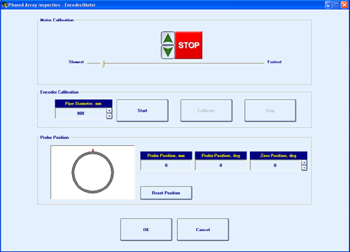
| Encoder: |
Incremental TTL encoder
Single Axis - Line Scanning
- Incremental TTL encoder
- Time-based (built-in real time clock ñ 0.02 sec resolution)
Multi-axis (on request): incremental TTL encoders
|
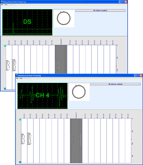
| Postprocessing: |
Freely distributable viewers for the computer running under W'XP, W'7, W'8, W'10 providing comprehensive postprocessing according to the corresponding AUT software applications and featured with:
Recovery and play back of A-Scan sequence at various gain levels
Echo-dynamic pattern analysis
Defects sizing, outlining, pattern recognition
Defect list creation
Converting data into ASCII / MS Excel / MS Access / MS Word formats
etc
|
| Real Time Hardware Outputs: |
67/134 (ISONIC AUT 16/32) independent user programmable digital lines (+24V or +9V logic) for controlling:
- Audible alarm sirens
- Paint guns
- GO/NO-GO parts sorters
- etc
16/32 (ISONIC AUT 16/32) independent user programmable analogue output lines (0Ö5V):
- TOF proportional
- Amplitude proportional
|
| Hardware Control Inputs: |
3 independent user programmable lines for the external pedal / push-button ìStart/Stop Inspectionî control |
| On-Board Computer CPU: |
Dual Core Intel Atom N2600 CPU 1.6 GHz / units manufactured after 2018-05-31
AMD LX 800 - 500MHz / units manufactured on or before 2018-05-31
|
| RAM: |
2 GB / units manufactured after 2018-05-31
1 GB / units manufactured on or before 2018-05-31 |
| Quasi HDD: |
SSD Card 64 GB / units manufactured after 2018-05-31
CF Card 4 GB / units manufactured on or before 2018-05-31 |
| Standard Ports: |
2 x USB (optionally expandable up to 8)
Ethernet
sVGA
|
Controls: |
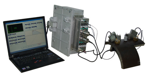
Standard USB Keyboard and Mouse connected directly to the instrument along with the sVGA screen
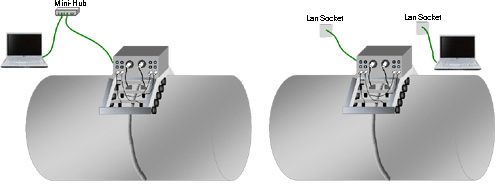
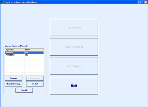
Remote control from an external PC over LAN (Ethernet) or internet
|
| Operating System: |
W'7PROEmb / units manufactured after 2018-05-31
W'XPEmb / units manufactured on or before 2018-05-31 |
| Motors (on request): |
3 independent outputs
DC powering: 48VDC
RS 232 control - stepped motor
Other type of motor / PC power voltage / Extra-motors - on request
|
| Power: |
Mains - 100Ö240 VAC, 40Ö70 Hz, auto-switch
36...72 VDC
Built-in UPS (uninterruptible power supply)
|
| Ambient Temperature: |
-50∞C ... +60∞C (operation)
-50∞C ... +60∞C (storage)
|
| Housing: |
Rugged aluminum case mountable on scanner
IP 67
No air intake
No external cooling required
|
| Dimensions of electronic box: |
305X160X380 mm (12.00"x6.30"x14.96") |
| Weight: |
7.500 kg (16.50 lbs) |