

|

|

|

|

|

|

|

|

|

|

|

|

|

|

|

|

|

|

|

|

|

|

|

|

|

|

|

|

|

|
PA UT (PAUT): Drill Rods

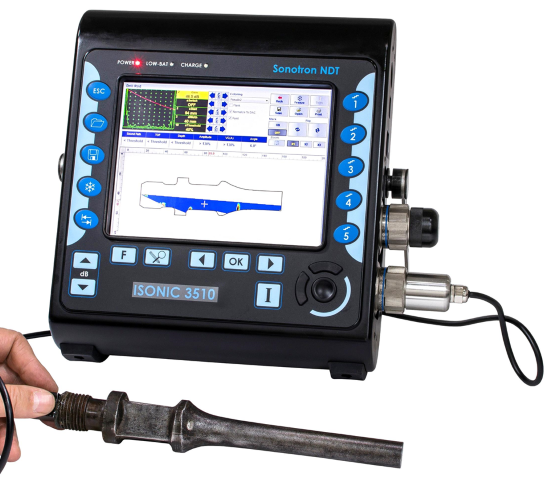

The outer shape of the drill rod is imported from the CAD drawing
The inspection is performed through the sectorial scan compression wave insonification of the material by means of PA probe situated at the accessible side end surface of the drill rod. Whilst implementing the desired sequence of pulsing receiving cycles (Scan Plan) each focal low is characterized by the individually settled focal point “travelling” along the outer surface of the rod, and the corresponding time base; the sensitivity is equalized within entire insonified section of the material through use of the independent mechanisms of Angle Gain Compensation (AGC) and DAC/TCG acting simultaneously thanks to the unique ability of ISONIC Series PA instruments: the DAC / TCG mechanism is used purely for compensating the dependency of echo amplitude on the material travel distance while the feature of varying Gain per Focal Law voluntarily is utilized just for the forming of easy-reproducible AGC plan. Both the DAC / TCG and AGC plans are created independently on each other with use of the same set of reference reflectors. The sharp focusing is provided through utilizing the full aperture for the firing and receiving of the signals
At last the whole volume of the material is inspected in one revolution of the PA probe moving around the end surface. The homogeneous sensitivity and true-to-geometry cross-sectional coverage and imaging are provided so for every radial position of the PA probe along with 100% raw data capturing and “on-the-fly" forming of the unfolded C-Scan imaging. On completing the scanning revolution the 3D image of the drill rod and automatically created editable defect list are available immediately. True-to-geometry imaging allows easy distinguishing between the defects indications and geometry echoes
|

ISONIC DRILL ROD software is featured with:
- Built-In Drill Rod Geometry Editor and Ray Tracer - Scanning Pattern (Scan Plan) Design
- Intuitive Image Guided PA Pulser Receiver with Beam Forming View
- True-To-Geometry Cross-Sectional Coverage of the Drill Rod and probe rotation scanning around the end surface of the part either encoded or time based
- "On-the-fly" True-To-Geometry Drill Rod Overlay Volume Corrected Imaging:
- Cross Sectional Slices
- Top (C-Scan) View - Unfolded
- 3D View
- DAC / TCG Data / Image Normalization
- Independent on TCG Angle Gain Compensation / Gain Per Focal Law Correction
- 100% Raw Data Capturing
- Automatic Defects Alarming Upon C-Scan Acquisition Completed
- Automatic Creation of Editable Defects List
- Comprehensive Postrpocessing Toolkit Including:
- Recovery and Evaluation of the Captured A-Scans from the Recorded Cross Sectional Views and C-Scans
- Recovery of the Cross Sectional Views from the Recorded C-Scans
- Converting Recorded C-Scans or their Segments into 3D Images
- Off-Line Gain Manipulation
- Off-Line DAC Normalization of the Recorded Images / DAC Evaluation
- Numerous Filtering / Reject Options ( by Geometry / Position / By Amplitude db-toDAC / etc ) and Regeneration of the Corresponding of Editable Defects List and Storing it into a Separate FIle
- Defects Sizing
- Automatic creating of inspection reports - hard copy / PDF File
DOWNLOAD AND PLAYBACK THE EXEMPLARY INSTRUMENTS FILES
|
