

|

|

|

|

|

|

|

|

|

|

|

|

|

|

|

|

|

|

|

|

|

|

|

|

|

|

|

|

|

|
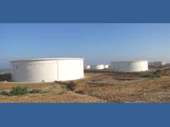
PA UT (PAUT): Annular Rings
Distinguishing and sizing of the following imperfections is provided:
- Scattered corrosion at the product side in the critical zone, tank shell and fillet weld areas of the annular ring
- Scattered corrosion at the soil side in the critical zone, tank shell and fillet weld, protrusion areas of the annular ring
- Compact damages (pitting, etc) at the product side in the critical zone, tank shell and fillet weld areas of the annular ring
- Compact damages (pitting, etc) at the soil side in the critical zone, tank shell and fillet weld, protrusion areas of the annular ring
- Loss of fillet weld metal at the product side
- Cracks and other defects inside fillet weld metal


|

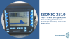
The ISONIC EXPERT A-Ring inspection software option is available for the ISONIC 3510, ISONIC 2010, and ISONIC 2009 UPA Scope instruments and featured with:
- Multiple skip shear wave True-To-Geometry Sector-Scan Cross Sectional Coverage and Imaging of the Annular ring critical zone and Fillet weld areas - Cross Sectional and Top (C-Scan)- / Side- / End- View and 3D
- Intuitive Image Guided PA Pulser Receiver with Beam Forming View
- Intuitive Image Guided PA Pulser Receiver with Beam Forming View
- DAC / TCG Normalization
- Built-In Annular Ring Fillet Weld Area Geometry Editor and Ray Tracer - Scanning Pattern (Scan Plan) Design
- Built-In Fillet Weld / Annular Ring Geometry Editor and Ray Tracer - Scanning Pattern (Scan Plan) Design
- Independent on TCG Angle Gain Compensation / Gain Per Focal Law Correction
- Automatic Coupling Monitor
- Encoded and Time based C-Scan
- 100% Raw Data Capturing
- FMC/TFM Protocol for the data acquisition and imaging
- Automatic Defects Alarming Upon C-Scan Acquisition Completed
- Automatic Creation of Editable Defects List
- Comprehensive Postrpocessing Including:
- Recovery and Evaluation of Captured A-Scans from the Recorded Cross Sectional Views (Sector Scan) and C-Scans
- Recovery of Cross Sectional Views from the Recorded C-Scans
- Converting Recorded C-Scans or their Segments into 3D Images
- Off-Line Gain Manipulation
- Off-Line DAC to TCG / TCG to DAC toggling for all types of stored files (A-Scans, cross-sectional views, C-Scans, etc)
- Off-Line DAC Normalization of the Recorded Images / DAC Evaluation
- Numerous Filtering / Reject Options ( by Geometry / Position / By Amplitude / dB-to-DAC / etc )
- Defects Sizing including the Quantitative Evaluation of the Thickness Loss
- Creation of Defect List and Storing it Into a Separate File
- Automatic creating of inspection reports - hard copy / PDF File
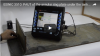
The movies below illustrate the inspection of the critical zone of the annular ring plate (the fillet weld area continued to up to 100 mm / 4 inch inside the tank) with use of ISONIC 3510 instrument utilizing either manual or automated scanning
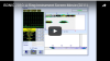
The movie below illustrates the instrument screen (ISONIC 2010) whilst performing scanning of the sample of the annular ring plate with the fillet weld including:
The video below illustrates the data analysis and interpretation for the record made for a segment of annular ring with real defects
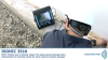
Inspection of the critical zone is a part of the complete solution based on the scanning above the protrusion surface; the complete solution is shown in the videos below:
Note: In order to accelerate the data stream the videos above are linked to the Youtube. In case the YouTube may not be accessed from your location please use the links below

|
|
|

|

|

|
|
|
|
|
|
|

|
DOWNLOAD AND PLAYBACK THE EXEMPLARY INSTRUMENTS FILES
|
